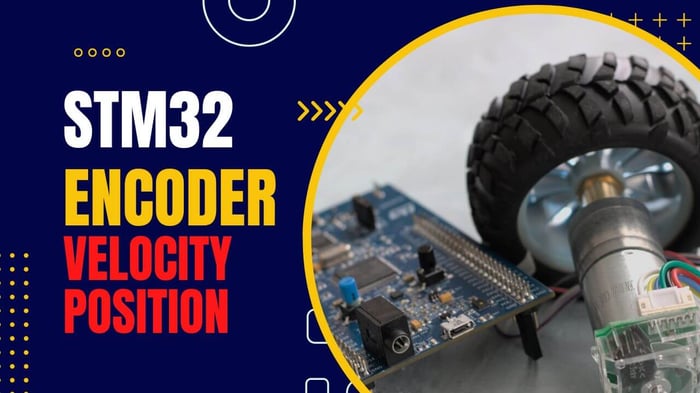
This article aims to deliver concise yet complete guidance on reading encoders using STM32 Timer Encoder Mode. First, I will explain how encoders operate. Then, we will discuss how to configure the timer in encoder mode. Finally, we will compute the distance and velocity of the motion.
Timers are a powerful tool in microcontrollers to handle various problems, from keeping track of time to generating digital signals. Although these functionalities are well-known to the general audience, most people are unaware that timers can be used to read Encoders. With minimum effort, you can use the encoder mode of timers to read the rotary position of a motor or identify the linear position with very high precision.
STM32 Timer Encoder Hardware and Tools
For this tutorial, I will use the STM32F411E-DISCO board, a rotary encoder embedded in a motor (GA25-371). In your case, you can use any other type of STM32 MCU and encoder. STM32CubeMX and HAL API will be the primary programming tools in this tutorial.


An operating principle of Encoders
The encoders have an optical transmitter and two receivers. If there is an object in front of the encoder, the light emitted from the transmitter will be reflected, and receivers can sense it. In other words, the encoder is an object detector at a basic level. However, the encoders have an additional component that makes them a powerful asset at an engineer's disposal: linear or rotary strips with evenly placed lines. When these strips are moved/rotated in front of the encoder, the receivers sense the presence of lines, and the output of the receivers will be a square-shaped signal with edges according to the number of lines passed. So, by counting the number of edges of the output signals, you identify the number of lines passed, giving the distance of a movement. This method can be adapted to the rotary condition using a rounded strip. Two receivers are to identify the direction of motion. By considering the phase shift in a signal, it is straightforward to determine the movement direction.

STM32 Timer encoder mode Configuration
As explained, the problem of distance estimation narrows down to computing edges of square-shaped signals and considering the phase between two signals to identify direction. We can handle this problem by using external interrupts or continuously checking the state of GPIO pins. However, these methods are neither efficient nor robust. It will consume a lot of computational power since operations are necessary very often. In addition, the microcontroller might miss detecting some edges, so the distance estimation will deteriorate over time. The remedy to these problems is to use the encoder mode in timers that automatically computes the number of edges and identifies the direction of movement. All mechanisms to handle the encoder are implemented at a hardware level, and your task would be to read the timer counter.
Next, I'd like to show how to configure the timer STM32CubeMX graphical. For that, choose 'Encoder mode' in the combined channels option, as shown in the figure below. The two channels of the timer will be dedicated to reading the output of the encoder. You can open the GPIO settings to see the pins to where the encoder needs to be connected: PB4 and PB5 in my case. Next, you configure other peripherals you need and save the file to the code to be generated.

Once the STM32 timer encoder mode is configured, we need to start the timer by calling HAL_TIM_Encoder_Start function:
HAL_TIM_Encoder_Start(&htim3, TIM_CHANNEL_ALL);Then, the timer counter will vary according to the movement of the strip with respect to the encoder. In other words, the counter provides the movement distance. However, there is one problem that we need to address: the counter can neither become negative nor exceed the Auto-reload value. It is vital to consider these limits to get a correct position value.
To tackle this problem, first, I define a struct containing three elements: velocity, position, and old counter value.
typedef struct{
	int16_t velocity;
	int64_t position;
	uint32_t last_counter_value;
}encoder_instance;
Inside the Timer update interrupt callback function that we covered HERE, we will periodically read the counter and estimate the position and velocity using the "update_encoder" function:
void HAL_TIM_PeriodElapsedCallback(TIM_HandleTypeDef *htim)
{
  timer_counter = __HAL_TIM_GET_COUNTER(&htim3);
  // measure velocity, position
  update_encoder(&enc_instance_mot, &htim3);
  encoder_position = enc_instance_mot.position
  encoder_velocity = enc_instance_mot.velocity
}
This function is presented below. If you are calling this function the first time, it assumes that the velocity is zero. Otherwise, we handle the overflow issues using a HAL API function that identifies the direction of motion: __HAL_TIM_IS_TIM_COUNTING_DOWN. Depending on the movement direction, we consider various overflow cases using 'if' conditions as shown below:
void update_encoder(encoder_instance *encoder_value, TIM_HandleTypeDef *htim)
 {
uint32_t temp_counter = __HAL_TIM_GET_COUNTER(htim);
static uint8_t first_time = 0;
if(!first_time)
{
   encoder_value ->velocity = 0;
   first_time = 1;
}
else
{
  if(temp_counter == encoder_value ->last_counter_value)
  {
    encoder_value ->velocity = 0;
  }
  else if(temp_counter > encoder_value ->last_counter_value)
  {
    if (__HAL_TIM_IS_TIM_COUNTING_DOWN(htim))
    {
      encoder_value ->velocity = -encoder_value ->last_counter_value -
	(__HAL_TIM_GET_AUTORELOAD(htim)-temp_counter);
    }
    else
    {
      encoder_value ->velocity = temp_counter -
           encoder_value ->last_counter_value;
    }
  }
  else
  {
    if (__HAL_TIM_IS_TIM_COUNTING_DOWN(htim))
    {
	encoder_value ->velocity = temp_counter -
            encoder_value ->last_counter_value;
    }
    else
    {
	encoder_value ->velocity = temp_counter +
	(__HAL_TIM_GET_AUTORELOAD(htim) -
              encoder_value ->last_counter_value);
    }
   }
}
encoder_value ->position += encoder_value ->velocity;
encoder_value ->last_counter_value = temp_counter;
 }
To check that code is working correctly, I will use the SWV plotter to plot the estimated position and velocity values. You can refer to this article to configure the SWV to do the same plots:
Finally, I debugged the code, and the estimated position varied according to the movement of the strip.

The video version of the STM32 Timer Encoder tutorial can be found here:

